Getting Started with the Oyster3 2G
Table of Contents
Let's assist you in getting an Oyster3-2G online for the first time.
In the Box
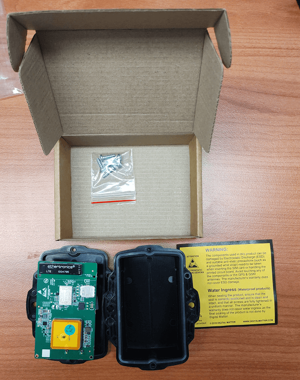
You will get a compact box containing the Oyster3 2G + standard housing. The 6 housing screws will be in a small packet inside the housing.
Provisioning Process
Electrostatic Discharge (ESD) Warning
The components used in the device can be damaged by Electrostatic Discharge (ESD). Suitable anti-static precautions (such as a grounded wrist strap) need to be taken when inserting the SIM card or handling the printed circuit board. Avoid touching any of the components or the GPS & GSM antennas. The manufacturer's warranty does not cover ESD damage.
1. Provision on the Tracking Platform
While this is not specifically required to 'fire up' a device, it is generally helpful to do this step first as it will mean if all goes according to plan, we'll simply see our device appear online in this platform.
Telematics Guru users can follow the guide here Creating Assets in Telematics Guru
2. Insert SIM Card
The device uses a Nano (4FF) SIM Card.
The device operates on 2G networks, and as such requires a specific SIM card from these networks.
Locate the silver SIM holder on the PCB. There is an image on the silkscreen which shows the SIM orientation
Slide the SIM into the holder with the keyed corner first and the SIM contacts orientated down to the main board. The image below shows the position of the SIM holder for the device.
3. Insert Batteries
Battery Selection
The Oyster3 2G requires 3 x AA LiFeS₂ batteries . Selecting a suitable set of batteries is critical to the overall device performance.
For more detail see Battery Suggestions
Key Requirements:
- 3.8 - 5.5V Input Voltage Range (use 1.5V cells)
- LiFeS₂ batteries are recommended for optimum performances, specifically Energizer Ultimate Lithium. These batteries
- Have good temperature tolerance (-20° -> +60°C operating range)
- Low rate of self-discharge - so long shelf and service life.
- Readily available at supermarkets or hardware stores and are user-replaceable.
If in doubt, speak to our support team.
Insert the batteries, following the markings on the battery holder indicating the polarity. The springs are the negative terminals.
4. Getting Online
Once the batteries are inserted, the internal LED will come on and flash. The device will do the following:
- Connect to the server: If the SIM card works the device will connect to the Device Manager and attempt to download any firmware and parameter updates then fetch fresh GPS-aiding data.
- Get a GPS Fix: The device will attempt to get a GPS fix. You can speed this up by moving to an area with good GPS signal.
- Reconnect to the server: The device will attempt to connect again to upload the result of the GPS Fix.
If the device does not complete these steps in 10 minutes, it will go to sleep and try again on the next heartbeat or the next trip start.
We are online!
Once these steps are completed, if all has gone to plan, we will be able to see the device on the map on our tracking platform.
The Device Manager Installer Page
Some users/installers may not have access to our end tracking platform, so the Device Manager Installer page can be used. It allows for a quick device check without giving away any sensitive information. It's also a handy tool for those with DM/TG access
Go to Device Manager - Installer (digitalmatter.com) and search for the serial number to confirm that it has:
- Connected
- Committed
- Obtained a position
Troubleshooting
In the rare event that the device does not connect, commit, or get a position. Troubleshooting steps are detailed below.
The device does not connect
- Check the LED is flashing, if the LED is not flashing, either:
- The device is in activation mode - and the magnet is still inserted, meaning it remains dormant - remove the magnet and try again!
- The device has not properly reset. Remove batteries for 20 seconds, and reinsert.
- The batteries inserted are dead. Test with a battery tester to check, or try a fresh set
- The device may have an issue, in which case contact DM for RMA information
- Confirm your SIM card is active
- It is worth trying a SIM card from another connected DM device if possible (as that SIM is proven working)
- Try a fresh set of batteries (they may have enough power to flash the LED but not enough to upload data)
- If it is your first time using a new type of SIM or network, you may need to apply certain network settings with a DMLink Cable.
The device does not commit
Typically, this is due to the device not yet being configured on the end server. Make sure this has been done.
See Since Committed/Since Connected and Troubleshooting for troubleshooting steps.
Sealing the Device
The device has an IP68 and IK07-rated housing. The device must be sealed carefully to achieve the IP68 rating.
It is difficult to provide an exact torque figure with which to tighten screws. This is because upon first sealing the device, the screws cut threads into the nylon glass housing. So, on the first assembly, the screws may be quite stiff. If the housing is opened and then resealed, the torque required for resealing will be lower than that of the first assembly.
The key goal we are trying to achieve in sealing is firm, even pressure on the silicone seal - as this is what keeps the device water-tight and dust-proof.
To achieve this:
- Ensure that the clear silicon seal is in good condition, is lying flat, and is not fouled by any plastic debris or other material.
- Close the housing, and gently squeeze it shut. The foam on the lid will compress against the batteries, holding them firmly in place.
- Tighten the 6 screws to uniform tightness - such that there is an even gap at all points along the interface between the base and lid.
- It is a good idea to use a screwdriver with a torque-limiting clutch, start with the screwdriver on the lowest setting, and gradually increase the torque until there is a small gap between the base and lid (no need to overtighten as you risk cracking the housing)
- The final torque when finished will be around 0.7Nm most of the time. (Value is a guide only)
Mounting and Installation
The device can be mounted onto an asset to be tracked using screws, bolts, cable ties, magnets, or industrial adhesives.
When choosing a mounting point, you have two competing goals
- To minimize the chances of the device being accidentally crushed, dislodged, or discovered by a thief
- To maximize the GNSS and mobile reception and provide adequate ventilation.
Key mounting notes:
- Avoid installing the box completely enclosed in a metal box
- Avoid installing in a location that will result in elevated temperatures. For instance, mounting the device in direct sunlight on the dash of a non-ventilated cabin may cook the batteries, leading to an abnormally short service life.
-
Try to orient the GNSS antenna towards the sky where possible (screw heads facing down): The best possible mounting location for optimal GPS reception is one that gives a clear, 180-degree view of the sky and is free from obstructions.
- If installing in a potentially low signal environment, check the signal strengths reported in the device data