Eagle - Getting Started
Table of Contents
The Eagle is a battery-powered data logger that provides GPS asset tracking while catering for an impressive array of inputs and outputs and different sensor interfaces. It comes in either 2G or 4G LTE Cat-M1 / NB-IoT versions.
digitalmatter.com
Datasheet & High Resolution Images
Eagle Downloads
View the latest tech-specs and high resolution device images for the Eagle
This guide will help you get up and running with the Eagle.
In The Box
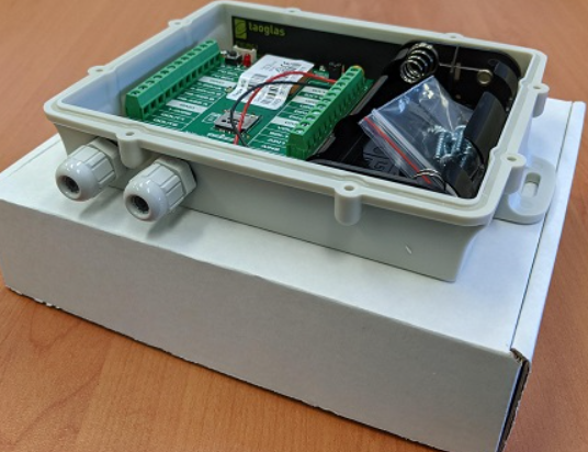
You'll get a compact box containing the Eagle and a small packet containing the 8 housing screws.
Setting It Up
Sim Card installation
The Eagle takes a 3FF Micro SIM card. The unit may be damaged by electrostatic discharge if not handled correctly so ensure adequate static precautions are taken. Consider wearing an anti-static wrist guard and avoid touching the antennae and any of the electronic components on the PCB. Take special care not to touch the ceramic GPS antenna as static can damage the sensitive GPS circuitry.
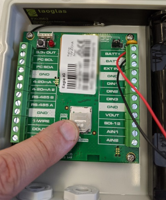
The SIM holder is located on the top side of the main PCB.
- Unplug the batteries and remove any external power connections.
- Slide the locking mechanism on the SIM holder to the “unlock” position, and lift the hinged portion of the SIM holder.
- Insert the micro SIM into the holder with the keyed corner orientated away from the hinge and the SIM contacts orientated down to the PCB (see example above).
- Close the SIM holder and slide the locking mechanism to the “lock” position.
Remember
Make sure once you're online, to declare your APN in the Admin parameters to ensure if you lose the network connection the device knows where to re-connect, and doesnt take time and battery life scanning through all known frequencies
APN AutoNet
For more information on Declaring APNs and the 4G AutoNet, see our knowledge base article here
Powering the Eagle
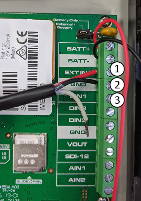
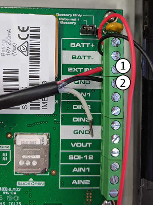
BatteryThe Eagle uses 4 x C-Cell batteries. Take care to insert the batteries with the correct polarity with the springs being the negative terminals. Once inserted, the LED next to the GPS antenna should flash briefly. If it does not, it means the unit has not yet reset. In this case, remove the batteries for a minute or two to allow any residual charge to drain, and then reinsert them. Failure to reset the unit will prevent automatic APN detection, and proper resetting of the battery life statistics The quality of the C-Cell batteries used has a significant impact on the reliability of the product. A single cell failure can render the device useless thus the importance of using good quality industrial C-Cells for maximum reliability. It is important to acknowledge the failure rate of the batteries – a 1% chance of a premature failure per cell equates to a 4% chance for the Eagle. The following batteries LTC cells are recommended: 'SAFT LSH14' External PowerThe Eagle has the capacity to be connected to either only Battery, or External power and Batteries. The Jumper at the end of the PCB above the BATT+ pin will decide which application is possible. It is set to Battery + External by default. The BATT+ and BATT- for the wiring in of the battery holder can take up to 16V, and the EXT+ (1) and GND (2) to be used for external power in are the same.
|
Housing
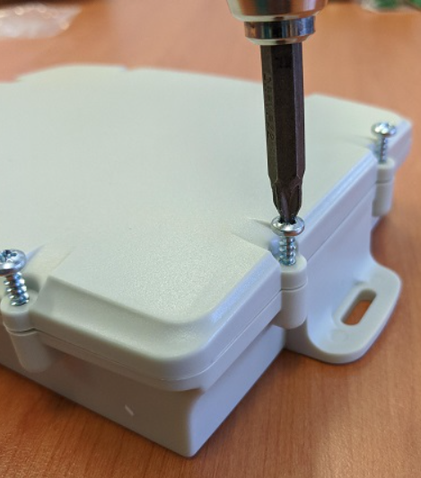
- Place the lid on the base, and gently squeeze it shut. Foam in the lid will compress against the batteries, holding them firmly in place when the unit is turned over. Warning: Be sure to place the lid the correct way around. The foam should be over the batteries. Screwing the lid down the wrong way will damage the base.
- Tighten the 8 screws to a uniform tightness. On the first assembly the screws may be quite stiff. An electric screwdriver with a torque limiting clutch is recommended.
- The screws used are a thermoplastic screw: 3.5mm x 12mm (BN82428).
- If you wish to replace the batteries and open the housing, be sure to check that the silicon seal is in good condition before closing the housing again.
Device installation
The Eagle can be mounted on the asset to be tracked using screws, bolts, cable ties, or industrial adhesives. When choosing a mounting point, you have two competing goals:
- To minimise the chances of the device being accidentally crushed or dislodged.
- To maximise the GPS and mobile reception, and provide adequate ventilation.
When using the Eagle as a battery powered device, reception is critical to its performance. While other members of the DM product family rely on their high quality GPS receivers for enhanced accuracy and the ability to operate in very low signal, a primary concern for the Eagle is the battery used during each GPS fix.
Getting Online
Once the batteries are inserted, the internal LED will come on and flash. If the SIM card works, the device will connect to the OEM Server. You can go to www.oemserver.com/installer and search for the serial number to confirm that it has connected recently.
The LED will flash slowly at first. When it opens a connection to the server, it will flash fast. Once data is sent, it will go solid briefly, and revert to flashing fast. When the device goes to sleep, the LED will switch off.
If the LED flashes but the Eagle does not connect, check the SIM is in the holder correctly and check that the SIM is working.
Troubleshooting Steps
Default Settings
| Heartbeat | 720 minutes (12 hours) |
| In Trip Logging Period | 120 seconds |
| In Trip Upload Period | 1800 seconds |
| Tracking Mode | Periodic Tracking |
Default I/O Mappings
The Eagle has the following digital inputs mapped by default, it is important to keep these in mind when mapping inputs to avoid clashes.
As seen below there are multiple sensors mapped to the same input in some cases. This is not an issue if only one of the sensors is used at a time. If they are to be used ensure to remap the default inputs, all is configurable via OEM.
Digital Inputs
| Digital Mapping # | Name |
|---|---|
| 0 | Trip Status |
| 1 | Digital Input 1 |
| 2 | Digital Input 2 |
| 3 | Digital Input 3 |
Status Flags
DM Device use "Digital Status Flags" contained in the Digital Input data field. In Telematics Guru - they are repackaged and mapped to Digital Inputs, as indicted below.
| Status flags | Name | Digital Input in TG |
|---|---|---|
| bit 0 | Trip Status | 24 |
| bit 1 | Battery Good Flag | 25 |
| bit 2 | External Power Good Flag | 26 |
| bit 3 | Connected to Server | 27 |
Analogue Inputs
| Analogue Mapping # | Name |
|---|---|
| 1 | MaximVoltage |
| 3 | Internal Temperature |
| 4 | Cellular Signal Strength |
| 5 | Loaded Battery Voltage |
| 6 | Battery Percentage remaining |
Ignition Wire
If you want a hard wired ignition on the Eagle, you simply need to insert the wire into the appropriate terminal (3) on the right hand side of the board next to the EXT power(1) in and GND (2)
