Eagle and Falcon - External Voltage Disconnects
Table of Contents
The Eagle and Falcon can be powered via Battery or External Power and/or Batteries.
The options are:
- 5-16V external power only (i.e. just hard wire to power)
- Battery power only
- Eagle: 4 x C Cells in the included battery holder
- Falcon: 3 x AAA in the attached battery holder
- Both - whichever is the higher voltage will be used.
For the last option, the batteries are used as a backup option should the External Power supply be interrupted. The device will simply use whichever provides the higher voltage.
If External Power is interrupted the device will keep functioning via the backup battery making it difficult to detect the interruption in External Power, up until the batteries get depleted. Additionally the Eagle and Falcon only report one voltage reading (Supply voltage) in Analogue 1.
External Power Removed Detection and Alerts
Our hard-wired, vehicle tracking devices such as the G62, Dart2 and G120 use back up Li-Po batteries to provide power for a while after a power disconnect. This provides enough time for the device to send an alert immediately once it detects the external voltage has dipped below a certain level. So if the unit is tampered with or otherwise loses power, we will know quickly so that we can rectify. This is catered for in both hardware and firmware in these devices as part of the design, as these devices should be hard wired to power at all times so it is important for us to know about disconnects.
On the Eagle and Falcon, the operation is slightly different, they do not cater for instantaneous external power removal uploads.
Eagle
In hardware, the external power removal will be detected immediately, and the "external power good" (bit 2 of the digital status flags) is set to 0. However this will only be seen on the server on the next upload, when this occurs will be dependent on your settings.
Falcon
The Falcon hardware does not cater for instant external power removal alerts. Instead, a lack of external power is determined by sampling the current draw when the device is attempting a GPS/WiFi fix. So this means we need to wait until this next occurs, which may be a long time, depending on the settings in use. Once a fix is attempted the "external power good" (bit 2 of the digital status flags) is set to 0 - so we can alert on this.
So how do I see if we are on external power or batteries, and alert on it?
1. Wire to a Digital Input (instant alerts required)
If we have a digital input free, we can simply connect our power source to here as well as the external input on the device. This means when there is an external power cut, the Digital Input will immediately detect this, and can be set to immediately upload also. For details see Common Concepts - Digital Inputs.
2. Monitor the Loaded Battery Voltage Level.
The Loaded Battery Voltage is reported in Analogue 5. This value samples the supply voltage at a time of high load (i.e. when the modem is on). In contrast, Analogue 1 (Supply Voltage) is measuring the same thing, but samples at a period of low load. There is also some smoothing, to prevent our values bouncing all over the place.
If there are clear differences between our external and battery voltage level, we can use the value of the Loaded Battery Voltage to tell when we are on battery vs external power. Note we will be waiting until the next update to see this change on the server. We can set alerts if required.
3. Monitor/Alert on the "External Power Good" Flag
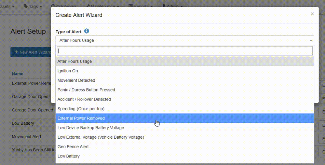
In TG, this means just setting up the "External Power Removed" alert from the alert wizard. It will work in the same way for any other hard wired device, we just need to keep in mind this won't be instantaneous.

For those using a 3rd party server, this is bit 2 of the status flags in the Digital input data field. Alternatively, on the Eagle this flag can be also made to appear as one of the other digital inputs via the method below:
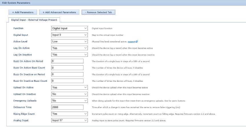
The Eagle has a Digital Input - External Voltage Present System Parameter tab which can be used to monitor the presence of External Voltage. The setup shown here will simply map the "External Power Good" flag to an additional digital input, which we can alert on if we like.

Function:
This is the Digital Input Function. You would select 'Digital Input'.
Digital Input:
Select the Input you want to Map the Input to. Input 9 is selected in this example.
Active Level:
Active Level is set to low.
Log On Active:
Yes as we want the device to log a record when the Digital Input is active.
Log On Inactive:
No.
Buzz On Active On Period:
0
Buzz On Active Buzz Count:
0
Buzz On Inactive Period:
0
Buzz On Inactive Buzz Count:
0
Upload on Active:
Yes, as we want the device to initiate an upload when the Digital Input is active.
Upload on Inactive:
No.
Emergency Uploads:
No.
Debounce Time:
2000. This is the time the Digital Input must remain active for the Digital Input change to be considered. This is to prevent false triggers.
Rising Edge Count:
Yes.
Analog Input:
Input 17.
This digital input is set to High (1) when External Power is present and unset (0) when External Power is disconnected.
