Using Integration Documents to Create a Downlink String
A downlink string is a combination of Hex values that triggers the configuration of a device OTA. The downlink string should be sent to the device to effect changes in parameter settings.
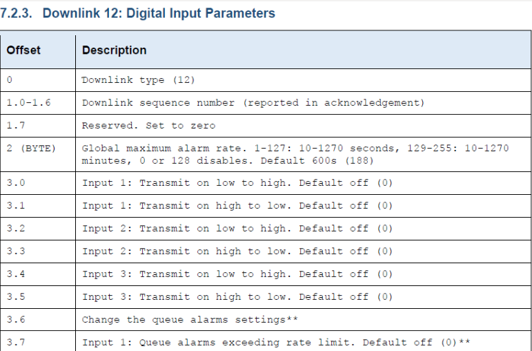
Here's an example of a downlink string created with Reference to section 7.2.3 of the SensorData/SensorNode Sigfox LoRa Integration document.


The table below shows an example of how the downlink (12) to set Digital Input parameters for a SensorNode OTA was derived
| Offset | Hex | Description | |
| 0 | 12 | 0C | Downlink 12 at default DEC value 12 |
| 1 | 00000001 | 01 | Binary to Hex |
| 2 | 134 | 86 |
Set Global Max Alarm rate to 1 hour: using the minute range of 129-255. 60 mins = DEC value 134 derived from the range – i.e. 129=10 minutes, 130=20 minutes, 131=30 minutes…etc |
| 3 | 00000000 | 00 | All Alarm Statuses for digital inputs Set to OFF (Binary)0000 0000 |
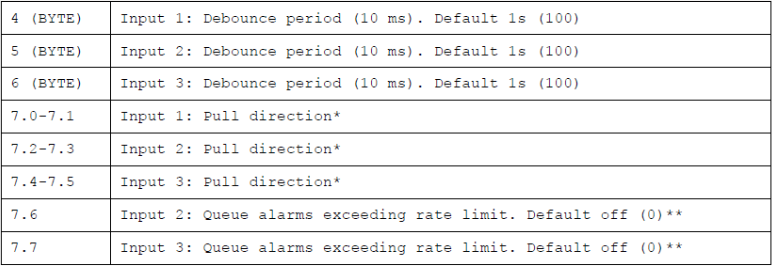
| 4 (Byte) | 30 | 1E | Set Debounce period to 30 seconds |
| 5 (Byte) | 0 | 00 | Disable Debounce for DI2 |
| 6 (Byte) | 0 | 00 | Disable Debounce for DI3 |
| 7 | 11 | 03 | Set Pull Direction to Pulldown on Digital Input1 Binary 0000 0011* |
|
Sigfox Downlink String:0C0186001E000003 LoRaWAN Downlink String:0186001E000003 Using Port 12 |
Important Notes
*Some Documents have the hour range, if an hour range is available for the device being configured then the minute range only applies up to 59 minutes.
*All Binary inputs are set in reverse from right to left i.e. 0011 (inputs 1 & 2 are set to Active; 3 & 4 are Inactive)
*The form taken by Time values being configured should follow absolute values. E.g. the Alarm rate can not be set to 5h:30min:10sec. In this case we will have to round off the time to 6 hours or 5 hours, whichever suits your requirements best. Thus setting the Alarm rate to 5 hours - 300 mins (DEC:158=HEX:9E)
Further examples are available below.
