Oyster Sigfox Default IO Mappings
This article explains the default IO mappings for an Oyster Sigfox device on Telematics Guru (TG).
Note that this is specific to Telematics Guru. Other front end systems may represent the data differently.
Each GPS position record logged by the device is sent immediately on the Sigfox network. If it is received by a Sigfox base station and correctly relayed to TG, it will be recorded by TG's as device telemetry The location information and device telemetry will be stored with some additional data from Sigfox about the transmission (RSSI, SNR, Average SNR, Sequence Number).
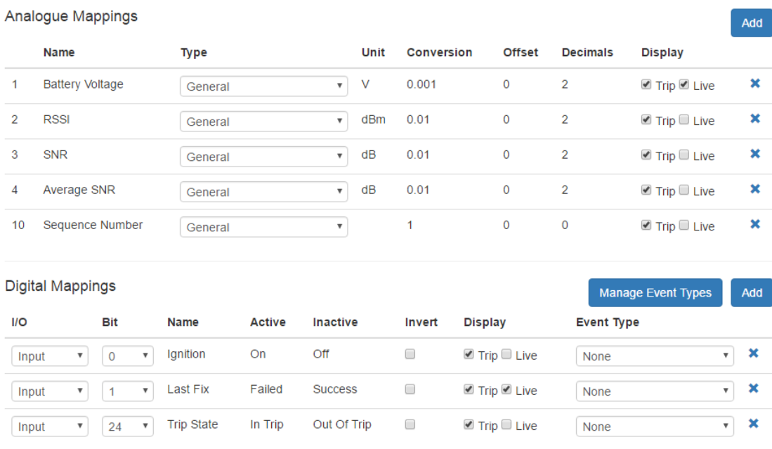
Analogue Mappings:
- An1 = Battery Voltage: in volts. Depending on the battery chemistry, the remaining capacity may be deduced from this.
- An2 = RSSI: the signal strength (in dBm) of the transmission received by a base station.
- An3 = SNR: the signal to noise ratio (in dB) of the transmission received by a base station
- An4 = Average SNR: the average signal to noise ratio (in dB) computed from the previous 25 messages. This may be empty. At least 15 messages must have been received.
- An10 = Sequence Number: the sequence number of the message, as sent by the device. This is useful to pick up messages that were not received by any base station.
Digital Mappings:
- DI0 = Ignition On/Off: the device is in or out of a trip
- DI1 = Last Fix Success/Failed: the last fix that the device attempted either succeeded or failed. Success means it obtained a GPS fix that meets the requirements, as setup in the system parameters. Failed means that it could not obtain a fix in the allowed time. Simply put, the GPS fix timed out.
- DI24 = Trip State In Trip/Out of Trip: the device is in or out of a trip. On this device, DI24 will match DI0.
This is a screenshot of the default setup on Telematics Guru:
