G150 Harness Definition

Written by Brandon MacKenzie
Updated at May 7th, 2024
Table of Contents
The G150 has two harness headers, which cover 10 pins each. The G150 comes with a single harness.
This covers powering the device plus commonly used IOs. If the application requires additional IOs - the second harness should be purchased when ordering G150s. Both harnesses are identical and can be used as either Harness 1 or Harness 2.
Specification:
- 1m long, 10 wire harness.
- 15 mm is pre stripped on the loose ends of the input (red), ground (black) and the ignition (white) wires.
- 24 AWG
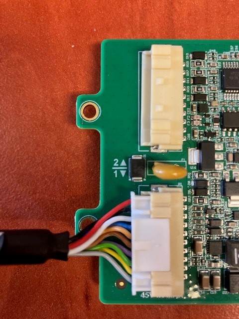
Depending on which header slot the harness is plugged into, the pins are either defined according to Harness 1 or Harness 2. The silkscreen on the PCB indicates which header designates which harness. Commonly used I/Os are available via header 1.
In the image below, the harness is plugged into the header slot for Harness 1, as indicated by the white arrow on the silkscreen of the PCB.
Harness 1 Wire Definition
| PIN | COLOUR | FUNCTION |
| 1 | RED |
VIN |
| 2 | BLACK |
GROUND |
| 3 | WHITE |
IGNITION |
| 4 | BLUE |
DIGITAL INPUT 1 |
| 5 | PINK |
VOUT DRIVER ID |
| 6 | BROWN |
DRIVER ID 1 (iButton Data / Wiegand D1 / TTL TX) |
| 7 | PURPLE |
DRIVER ID 2 (Wiegand D0 / TTL RX) |
| 8 | GREEN |
SWITCHED GROUND 1 |
| 9 | YELLOW |
ANALOGUE INPUT |
| 10 | GREY |
GROUND |
Harness 2 Wire Definition
| PIN | COLOUR | FUNCTION |
| 1 | RED |
DIGIN 2 |
| 2 | BLACK |
DIGIN 3 |
| 3 | WHITE |
DIGIN 4 |
| 4 | BLUE |
RS232 RX |
| 5 | PINK |
RS232 TX |
| 6 | BROWN |
VOUT |
| 7 | PURPLE |
GROUND |
| 8 | GREEN |
CAN P |
| 9 | YELLOW |
CAN N |
| 10 | GREY |
SWITCHED GROUND 2 |
Driver ID Lines
Driver ID 1 and Driver ID 2 are used for various functions depending on configuration. Either:
- Driver ID 1 can be used as the iButton Data Line
- Driver ID 1 and 2 can be used to connect a Wiegand Driver ID reader or a DM RFID reader To see how to connect the RFID reader please see the following article. Driver ID Options
Connector Part Number
Some partners may wish to make their own custom housings/harnesses. If that is desired, the relevant part is PAP-10V-S