Falcon Cellular - How to setup analogue sampling
This article explains how to setup the Falcon Cellular device for analogue sampling. We will consider an analogue sensor that can be powered by the 3.3V output from the Falcon.
Other sensor types may need a larger voltage. Consider using the battery voltage and switched ground to power these. This is not covered below.
Wiring:
Ground pin of the sensor connects to the GND pin on the Falcon (PIN no. 7, counting from the left where V-IN+ is PIN 1)
Supply voltage pin of the sensor connects to 3.3V pin of the Falcon (PIN no. 10) - assuming our sensor takes 3.3V power.
Analog output pin of the sensor connects to A-IN1 pin of the Falcon (PIN no. 5)
Here is an example of the senor wiring interface:

System Parameter Settings:
In this example we would like the Falcon to only power the sensor 1 second before taking the measurement to avoid draining the batteries.
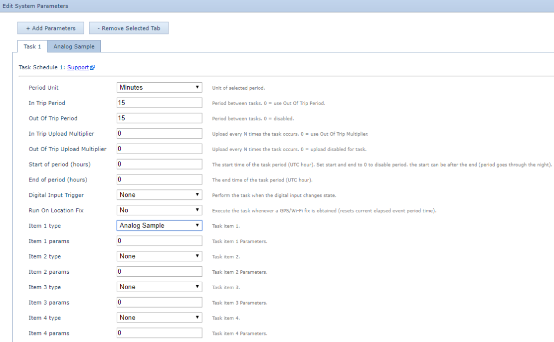
This can be controlled under the ‘Analog Sample’ Parameter settings. We will also need to setup the ‘Task 1’ parameter settings to sample the analog input.
Analog Sample Parameter Settings
- Enable the 3.3V Output.
- Set the ‘Power Delay’ to 1 second – this will set the Falcon to power the sensor with 3.3V for 1 second before taking the sample measurement.
- The "analog input" is set to input 7. The voltage value (in mV) will be saved to analogue 7.

Task 1 Parameter Settings
- Set ‘Item 1 type’ to ‘Analog Sample’ to set the Falcon to sample the analog input.
- This will take an analogue sample every 15 minutes, when in trip and out of trip.
- The upload multiples are 0, to disable uploads on readings. This means it will normally upload on the heartbeat, or other trip related upload reasons.
- We will add an alarm based upload in the next section - see below.

Setting an Analog Threshold:
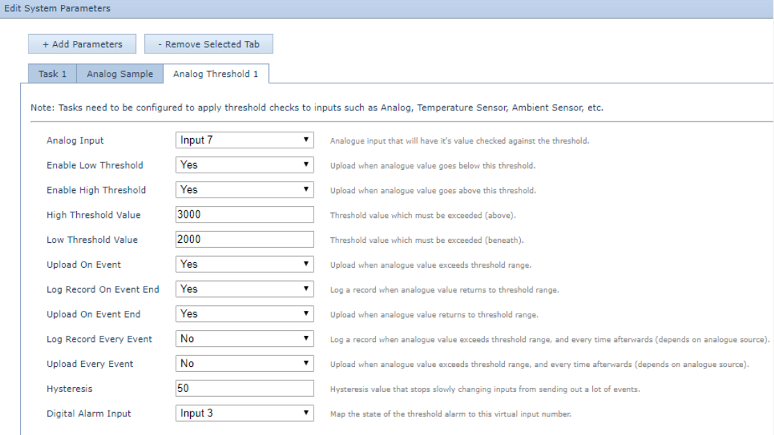
In this example we want to set a high threshold value of 3000mV and a low threshold value of 2000mV. The Falcon should upload when the analogue value exceeds the threshold range and when the analogue value returns within the threshold range.
Note: When setting up an Analog Threshold, it is important to have the above Task parameter set up.
Analog Threshold 1
- Set the ‘Analog Input’ to the analogue input that will have its value checked, in this case ‘Input 7’.
- Set ‘Enable Low Threshold’ and ‘Enable High Threshold’ to ‘Yes’.
- Set the ‘High Threshold Value’ to ‘3000’. Note that high is before low.
- Set the ‘Low Threshold Value’ to ‘2000’.
- Choose the logging and uploading parameters as required. Here we choose: set ‘Upload on Event’, ‘Log Record on Event End’ and ‘Upload on Event End’ to ‘Yes’.
- Hysteresis can be set to ‘50’ to allow some margin for voltages dithering around the thresholds - this could avoid many uploads if the value is jumping above and below the threshold.
- In this example, digital input 3 is turned on when the alarm is on. This is useful in some systems for triggering alarms.

Note: For more details on configuring Analog Thresholds, please visit this link.
