Troubleshooting - Battery Problems
Table of Contents
Possible reasons for unexpected battery drain include:
- Single-cell battery failure
- Most batteries have a failure rate of close to or under 1%, which varies by brand and type
- Battery age may adversely affect their performance.
- High and extremely low temperatures or extreme vibration can greatly increase the failure rate
- Activating Recovery Mode accidentally, and leaving it on
- Inappropriate configuration, leading to excessive uploads
- High levels of vibration, leading to excessive GPS checks
- Cellular network connectivity problems, leading to excessive upload time
- Rarely, a hardware fault, leading to sustained or sudden battery drainage
Diagnosing Battery Faults
If you have the unit in your hands, the best way to check for a battery fault is to measure the individual battery voltages with a battery tester unit that applies a load to get a genuine reading. This is a more accurate way of determining battery voltage & health than a multi-meter.
An Alkaline or Lithium battery (AAA or AA) has an initial voltage of 1.6 V, and less than 1.2 V - 0.9 V when depleted. An LTC cell (AA or D) has 3.6V when full and 3.2-3.0V when depleted. If one or two of the batteries has a low voltage, and the others are high, you can be sure you are looking at a battery failure.
Recommended Batteries
While always using fresh batteries is the start, there are further battery recommendations in our support article here
We do not recommend using Alkaline batteries on any Cellular device except for the Eagle which is able to take 4x Alkaline C Cells.
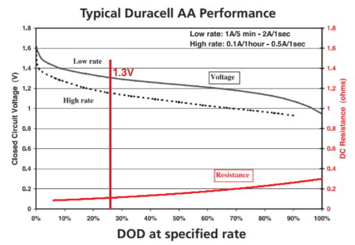
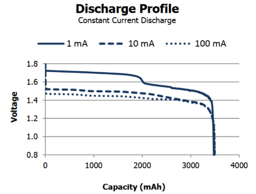
The Alkaline Battery discharge profile follows the below curve. Since our devices require the battery voltage available to be >4.0-4.2V (1.3-1.4V/cell) to operate, you can see this point is crossed fairly early. You can compare this to the Lithium Batteries (LiFeS2) battery discharge curve, the voltage stays above this point for the majority of it's life.
 |
 |
Battery Failure due to Temperature
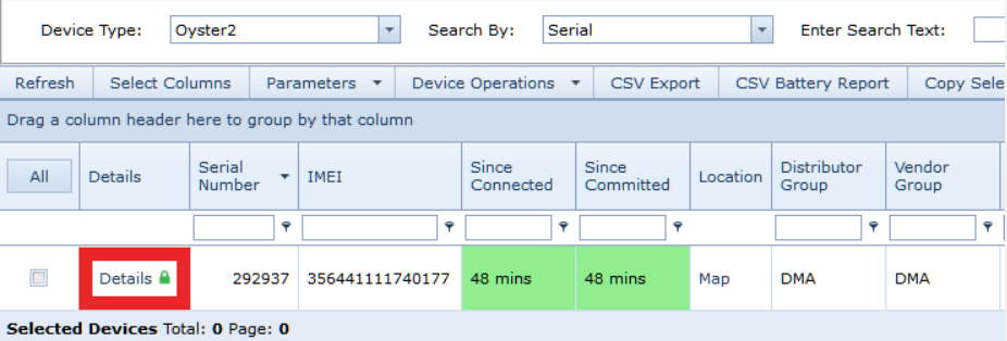
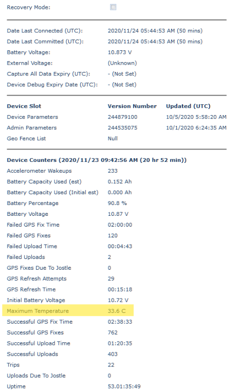
To determine if the failure was induced by temperature, you can check the maximum temperature reading on www.oemserver.com. First find your device, and click 'Details':
Then scroll down to find the Device Counters
Different types of batteries have recommended operating temperatures and temperature limits before risking the failure of the cell. While batteries can operate within these boundaries. the lifespan is altered accordingly the further the actual temperature is from the recommended temperature.
| Battery Name/Type | Battery Size/Voltage | Recommended Temperature | Temperature boundaries |
|---|---|---|---|
| Duracell Alkaline | AA & AAA - 1.5V | 23°C | -20°C ~ 30°C |
| Energizer Lithium | AA & AAA - 1.6V | 21°C | -40°C ~ 60°C |
| EVE LTC | AA & D - 3.6V | 25ºC | -60°C ~ 85°C |
| Green Energy LTC | AA & D - 3.6V | 23ºC | -55ºC ~ 85ºC |
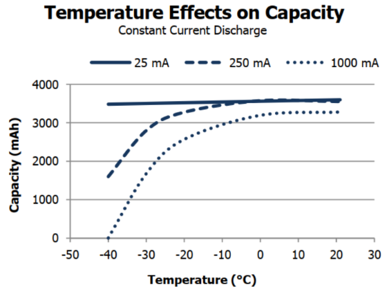
Below we can see the effect of negative temperature on the capacity of a battery cell. (Pictured is Energizer Lithium) When the temperature of a battery increases the performance of the battery increases as well until it encounters an internal resistance fuse or will experience cell failure and may explode.
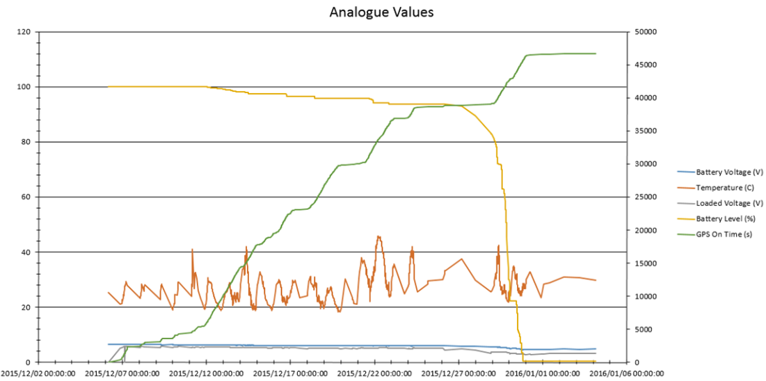
It may also be useful to graph the analog values of problem devices. On Telematics Guru, this can be done with the Asset Analogue Graph Report or if you are using a third-party server you can graph Analogue 3 which is standard for temperature across digital matter devices. In Telematics Guru, go to Reports > All Reports and the Asset Analogue Graph is under Data Exports.

A battery failure typically shows up in the graphs as a sudden drop-off as seen by the yellow line below.
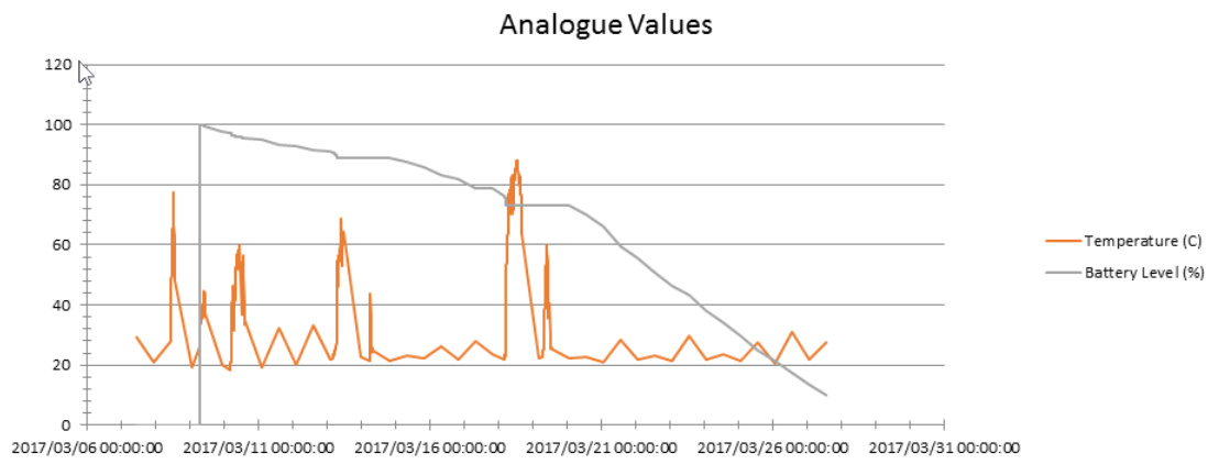
In the below example, you can see the effect of excessive temperature in an engine bay on the batteries over several weeks.
Low Battery Alert Setup on Telematics Guru
Having a low battery alert set up on Telematics Guru allows you to get notified when the battery reaches low levels or encounters the under voltage lockout so you may schedule battery replacement to ensure continued device functionality.
Low Battery Alert Set up
See our article on Alerts for the steps to create a low-battery alert on Telematics Guru
OEM Server System Parameters
Effect of High tracking rates on Batteries
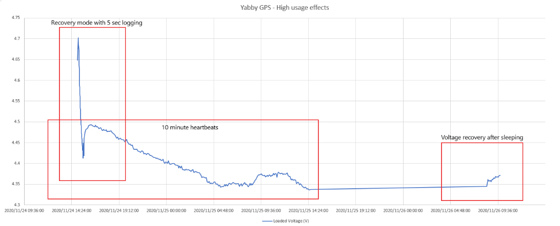
If you have high-resolution tracking or have recovery mode activated on a battery-powered device, these can drain the batteries faster than expected. Furthermore when you have a device on high levels of tracking, such as short heartbeat periods or logging the batteries will continue to decrease over time, then once the high-resolution activity stops the batteries will recover some voltage. This is why sometimes just going off the voltage reported isn't the complete picture.
Checking For Configuration Issues
Overview of Operations
To see how the devices wake up and measure trips see our support portal article here
In addition to checking the maximum battery temperature & whether recovery mode is on (green), the device details page is the best place in OEM Server to see if there have been excessive upload or GPS failures and whether the device is experiencing too many wakeups.
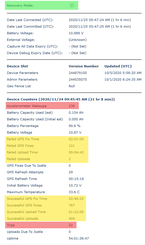
- Check that Recovery Mode is not checked
- Recovery Mode will automatically disengage after the configured time, or 12 hours by default.
- Check that the number of Accelerometer Wake ups (red) is not too much larger than the number of Trips
- It is normal for the Wakeup count to be 5-10 times larger than the Trip count
- More than this indicates that the unit is often being woken up by vibrations/bumps in between trips, which wastes power on a GPS fix
- If you are using the Upload On Jostle feature, the GPS Fixes Due to Jostle and Uploads Due to Jostle counts tell you how much extra energy the feature is using
- If you are wasting too much power on unwanted wake-up, consider increasing the accelerometer wake-up thresholds, changing your install location to avoid the vibration, or disabling the accelerometer altogether
- Check the ratio of GPS Fixes to Uploads
- It is most battery efficient to have 10 or more fixes per upload, because uploads use so much more battery than fixes
- The ratio is determined by the In Trip Logging Period and In Trip Upload Period, in the Basic Tracking section of the System Parameters
- Check the ratio of Failed GPS Fixes to Successful GPS fixes.
- if the unit is experiencing higher failed GPS fixes than successful it may be either mounted in a position where it can only achieve a valid fix in optimum conditions, or maybe operating extensively in marginal coverage, or both.
- Check this article for GPS troubleshooting

- Check the ratio of Successful Uploads to Failed Uploads
- A large number of failed uploads (>10%) could indicate a problem with the signal strength (bad install location), a problem with the antenna (cracked solder joint), or a roaming issue
- See this article for details on Cellular reception troubleshooting
Diagnosing Hardware Faults
While all devices go through comprehensive Quality Assurance check at production, hardware faults may occasionally develop in the field. Hardware faults that might manifest as a battery problem include:
- A cracked Cellular antenna.
- A faulty tamper-detection cable causing a slow battery drain (Specific to the Remora devices).
- A cracked capacitor causes a slow battery drain.
- Corrosion damage due to water ingress, causing a slow drain.
- A faulty modem or GPS causes a fast drain on each upload or GPS fix attempt.
To check for a cracked antenna, inspect the solder points where the Antenna meets the PCB.
Checking for issues by testing the current draw
Checking for the other issues involves measuring the device's current draw with a multimeter and/or bench-top power supply.
Note
These values are only a rough guide to module and device draws.
- Set your bench-top power supply for 6V
- Make extra certain that you connect the supply leads the right way around!
- Positive lead on the battery holder terminal with the red wire
- Negative on the terminal with the black wire and spring
- No seconds chances - The battery-powered devices do not have reverse polarity protection, if this happens the PCB will be irreparably damaged.
- If you want to accurately measure the sleep currents, set your multimeter to the milliamps range, and insert it between the supply and the device
- Now read the current levels off the bench-top supply or the multimeter
- Just after applying power, you should see 20-80 mA, while the cellular connection starts
- During the cellular connection, you should see around 100 mA
- After the cellular connection, the GPS fix starts, and you should see between 20 and 27 mA
- Eventually, the device will go to sleep. It should then read 0 mA.
- If you are using a multimeter, you can switch it to the uA range once sleep has started
- You should see a base current of around 3.3 uA
- Plus 7 uA if the accelerometer is enabled
- Plus 5 uA if the tamper detection board is present (Remora only) - try wiggling the tamper detect connector, and check if this increases the current draw
- Plus 16 uA if the GPS has seen satellites in the last 4 hours
- Mind that you change the range back to mA before waking the device, as it won't work on the uA range
If you observe excessive current or parts of the board heat up, your board may have developed a hardware fault in the field. If it is still under warranty, and hasn't been subjected to water damage, your distributor will be able to help you with further debugging, repair, or replacement.
