SensorData Sigfox - Configuration and Usage Guide
Table of Contents
The SensorData provides a number of configurable parameters, to allow its behavior to be tailored to specific applications.
Factors affecting the configuration you might choose include:
- How many Sigfox messages per day you have on contract
- How often you intend to change the batteries, and the type of batteries in use
- How good the GPS reception is in your installation
How the SensorData Connects
The SensorData broadcasts its status updates into the air, where they will be heard by nearby Sigfox towers while in coverage. These status updates are identified by the SensorData's serial number - a six to eight digit hex string, printed on the label. If the serial has been registered with Sigfox, and is on a contract, the messages are accepted and forwarded to a front-end website such as Telematics Guru. If you are an end-user, all you need to do is add your activated SensorData on Telematics Guru to begin receiving its updates. If you are a distributor, or have a private account with Sigfox, you also need to configure your units on the Sigfox backend according to this guide.
How the SensorData Uses Sigfox Airtime
Sigfox devices are provisioned on one of four monthly contracts:
- The One contract allows 2 uplinks and 0 downlinks per day
- The Silver contract allows 50 uplinks and 1 downlink per day
- The Gold contract allows 100 uplinks and 2 downlinks per day
- The Platinum contract allows 140 uplinks and 4 downlinks per day
The SensorData is configured for a particular contract by your dealer, and keeps track of the number of uplinks it uses throughout each day and throughout the monthly billing cycle. For example, using the One contract, on the 7th day of a 30 day month, the SensorData knows that it may have used up to 6 x 2 = 12 uplinks in the previous days of the month. It knows it has a budget of 2 uplinks in the current day, and 46 uplinks for the remainder of the month. If it finds that it did not use all 12 of the uplinks from the previous days, it considers them 'extra' uplinks, and may use them opportunistically to increase the detail of tracking. Once it has used them up, it is left with either the 2 uplinks allocated for that day, or with all 48 uplinks allocated for the remainder of the month, depending on how you configure the uplink budget strategy. Once it has run out of budget (for the day, or for the month), further uplinks are skipped.
How the SensorData is configured
Firmware updates (and optionally, configuration) are performed with a plug-in USB adapter, and a Windows configuration app. An adapter can be obtained from your SensorData distributor.
Download the config app here:
V1 PCB: https://www.oemserver.com/tools/SensorDataSigfox/ConfigTool/setup.exe
V2 PCB: https://www.oemserver.com/tools/SensorDataSigfoxV2/ConfigTool/setup.exe
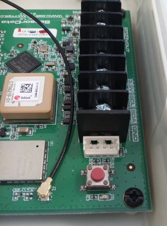
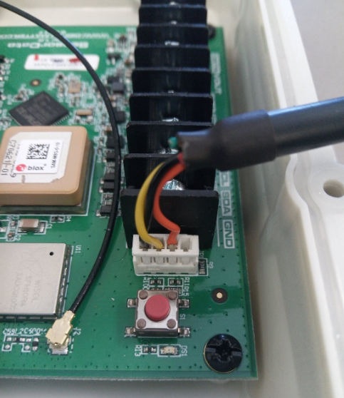
The adapter plugs into the four pin connector near the push button. If your adapter has a red wire fitted, it will supply power to the SensorData while it is plugged in. If it doesn't, you must power the SensorData with batteries during configuration.


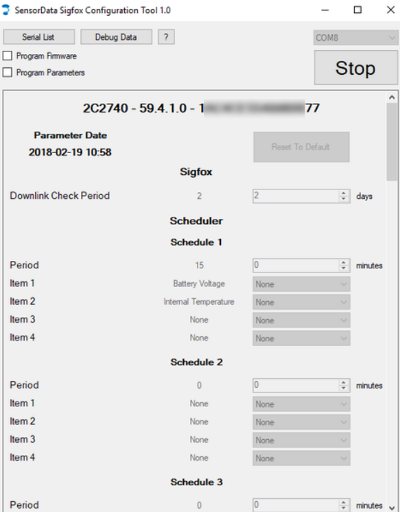
To read the available parameters, select your adapter from the drop-down list in the top right, and click Start. The configuration tool will read continuously, and display the currently programmed parameters in the center column. To program new parameters, enter the desired parameters in the right hand column, and check the Program Parameters button. Checking the Program Firmware button will additionally update the SensorData with the bundled firmware.

If you click the Serial List button, a list of scanned serial numbers will pop up. You can hot-plug the adapter into many SensorDatas in sequence to populate the serial list. When no changes are made to a SensorData, the serial is added in gray, and a chime is sounded. When the SensorData is programmed, the serial is added in black, and an alternate chime is sounded. After programming, the SensorData will take several seconds to reboot before it will be visible in the application again. It is not necessary to wait for this to occur before moving on to programming the next unit.
Configuration Options
The top line in the display shows the serial number, version string, and PAC code. In the screenshot above, the serial is 2C2740, the firmware version is 59.4.1.0 (product, hardware revision, major, minor), and the PAC ends in 77. The PAC is used when registering the SensorData with Sigfox for the first time, and is written on the unit's label, along with the serial.
The 'Reset To Default' button in the top of the right column resets the whole right column to the default settings. The settings are described below
Downlink Check Period:
How often the SensorData should check for downlinks.
Scheduler:
Out of the box, the SensorData Sigfox is not configured to take any readings, and must be first configured by setting up schedules. Currently, there can be up to 5 different schedules, each with 4 items, which represent a single data source (analog input reading, GPS position, battery voltage, etc). Each schedule is completely independent, but if 2 (or more) happen to occur at the same time, they will be run one after the after (without grouping data into transmissions).
Period:
In minutes, this is how often the schedule gets run. Care must be taken in choosing this value, in order to not exceed your uplink budget, as further uplinks will not be sent over the Sigfox network.
Item IDs:
Options are - Version, GPS Position, Battery Voltage, Analog Input 1, Analog Input 2, Digital Inputs (returns all digital input states), Digital Input 1 Count, Digital Input 2 Count, Digital Input 3 Count, Internal Temperature (Temp as measured by PCB temp sensor), DM Temperature Probe 1 (probe at I2C address 0), DM Temperature Probe 2 (probe at I2C address 1), DM Ambient Sensor, SDI12 Measurement 1, SDI12 Measurement 2, SDI12 Measurement 3, SDI12 Measurement 4, SDI12 Measurement 5
Enable 3.3V / Vout:
Enables the 3.3V or Vout output to power sensors when running the schedule. This is enabled at the schedule level: it is enabled for Power On Delay seconds at the start of the schedule, then kept active for each item in the schedule, and switched off after sampling is complete.
Power On Delay:
How many seconds to wait before running the schedule, after enabling outputs. Can be used to give external sensors enough time to power on fully. This delay is ignored if no outputs are enabled. Default is 0 seconds. This setting is provided in addition to the setting under the "analogue input 1/2" section to allow the power outputs to be use in a more flexible way (eg. power an on/off sensor before digital inputs are sampled).
SDI 12 Measurements
Currently, 5 are available
Vout Power Up Delay:
How long to wait after powering up the sensor until a reading is taken
Address:
SDI 12 address of the sensor, 0-9 - 0 is the default if using only 1 sensor
Measurement Type:
SDI 12 measurement number 0-9
Measurement Count:
Number of data points, 1-15
Data Conversion:
Soil Moisture (UINT8):
Values are packed into UINT8 fields. SMP = (Value in field / 2) - 5. Providing a range of -5 to 122.5 with 0.5 precision
Temperature (UINT8):
Temp = (Value in field / 2) - 40, yielding a range of -40 to 87.5 with 0.5 precision
Generic INT16 * 100
Allows a reading to be +-32767.00 with 2 decimal places
Generic INT32 * 1000 (not yet implemented)
Allows a reading to be +- 2 147 483 with 3dp
GPS
Devices are shipped with relatively loose requirements for a fix - shown below. This generally speeds up fixes and allows fixes in adverse conditions. Simply put, the device will minimise the time spent with the GPS on. This means that even in good signal conditions, a poor fix may be accepted
Fix Timeout:
Maximum time to spend for the GPS to get a position fix, per attempt. Default is 20s. This limits the battery drain if there is no GPS signal.
Minimum Required PDOP:
Position Dilution of Precision (PDOP) values below this value will be accepted
Minimum Required Position Accuracy:
Position accuracy values lower than this are accepted
Minimum Required Speed Accuracy:
Fixes with speed accuracy values lower than this are accepted
GPS Model:
This informs the GPS module of what sort of motion to expect from the asset, allowing it to make better estimates when moving. The Automotive setting is a safe default, but the Pedestrian and Stationary settings may be useful as well. Setting the model appropriately allows the GPS to filter out noise more effectively
Require 3D Fix:
When unchecked (False) 2D fixes are accepted.
Discard First N Fixes:
Discard this number of fixes once the accuracy requirements are met.
Digital Inputs
See here for an article on Digital Inputs
There are 3 digital inputs on the SensorData Sigfox. These can be used to monitor the state of external devices or switches, or to count pulses - from a rain gauge for example.
The inputs have a maximum input of 48V, and anything about 2.5V or above is considered 'on'.
Maximum Alarm Rate:
The minimum time between alarm transmissions. If an alarm occurs before this time has passed (from a previous alarm), it will be ignored. Default is 600s (10 minutes). This can prevent excessive uploads if for some reason an input stays at a certain value, and helps conserve your uplink budget.
Input Pull Direction:
Whether the input should be set to pull up or pull down. See here for more information.
Input Alarm on High/Low:
Enabling either of these will send an alarm message when the condition is met, i.e. Alarm on high enabled = sending message when the input turns on. Default is disabled for both.
Queue Alarms:
Queues alarms that would otherwise be dropped due to rate limiting. When rate limiting is enabled, each alarm event is followed by a hold-off period. By default, any events occurring within the hold-off period are dropped. When this parameter is enabled:
- Events occurring within the hold-off period will be deferred until the end of the period
- If multiple events occur for a particular input, only one event will be sent at the end of the period, for that input
- If events occur for more than one input, one event will be queued for each input. Lower numbered inputs will send their queued events first, followed by another hold-off period, and then higher numbered inputs.
Default is No.
Input Count Edge:
Sets if the input count is incremented when the input turns on, or off. Default is high (count when input turns on).
Input Debounce Period:
The input has to change for this amount of time for the change to be detected. Default value is 1000 ms (1 second).
Analog Inputs
The SensorData Sigfox has 2 analog inputs which can be used to measure voltages up to 30v. Outputs on the device can be enabled just before sampling, to power external sensors. Sampling occurs over roughly 100 ms, in which multiple readings are taking, and the average is calculated to be sent over the network. The following parameters are configurable:
3.3V Out on Sample:
Enables the 3.3V output to power sensors when sampling.
Vout on Sample:
Power on Delay:
Power
Vout Boost Enable:
When this is enabled, Vout will supply 12V to power external sensors when taking measurements. Otherwise 6V is supplied directly from the battery